
Apply Design Definitions
To access this panel:
-
Using the Planning ribbon menu, click Preparation.
-
Display the Apply Definitions tab.
Your product automates much
of the mine design process by using string attributes to define different
excavation types. The Design Definitions screen allows properties and constraints for all elements of
the design to be specified.
What is a 'Design Definition'?
A Design Definition is a self-contained instruction set that can be applied during mine layout operations to fast-track the repetitive task of defining precise constructional details for every string used. For example, you may wish to apply a standard cross-cut shape to a particular ramp string.
String types are differentiated by their name, which is the only aspect of a design definition that needs to be unique.
The basic procedure for using design definitions is:
-
Set-up the design definitions for a string or wireframe type.
-
Apply these definitions to a particular string or wireframe type.
-
When your layout is created (manually, or automatically), each string or wireframe type is automatically linked to its corresponding design definition.
If the Imported Wireframe design type is selected, the Imported Wireframe Checks option (Design >> Validation) must be run before applying the corresponding design definition.
Matching Attributes
In versions prior to version 2.1, Studio UG matched designs to definitions by the field DESIGNDF (the design definition Name). In these versions, you had to ensure you applied the design definition to your designs. Applying a design definition to a design would set the values of the DESIGNDF, COLOUR, LSTYLE, and SYMBOL columns. During processing, the design definition of a design was only matched by reading the values in the DESIGNDF column. This could lead to a mismatch between the value of DESIGNDF and the display Properties (COLOUR, LSTYLE, SYMBOL) if you modified the display properties of your designs without using the Apply Design Definitions feature. In effect, there was a risk of data duplication that could get out of sync.
In Studio UG version 2.1 and later designs are once again matched to design definitions by matching attribute values. This means that if the attribute values are on the design, you don't need to apply the design definition as it will automatically be matched during processing. The action of applying a design definition sets the matching attribute values on the designs so that the automatic matching will work. This provides more flexibility and can save significant amounts of time. If the designs already have the appropriate attribute values, you can jump straight to processing. To apply values to the matching attributes, you can use the Apply Design Definitions screen, standard Studio commands, or even use a script.
You can select one or more attribute definitions to use for matching. Each design definition must have a unique combination of values for the matching attributes. The matching attribute definitions are defined per design type. You can still match using the display properties (LSTYLE, COLOUR, SYMBOL), but you are no longer restricted to doing so. Matching on fields other than the display properties allows you to use the same design definition for designs that have different colours, for example. Activity Solids get their colour from their associated design, whether COLOUR is used in the attribute matching or not.
In a way this is how Studio 5D Planner worked: it was just hard-coded to match by the attributes COLOUR, LSTYLE, and SYMBOL. In Studio UG, this restriction is lifted.
Each design type must match on at least one attribute. You can choose to match on the system attributes COLOUR, LSTYLE, and SYMBOL or any of the user attributes. The design definition needs a unique name as well.
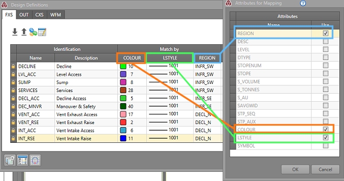
These "Match By" attributes are configured using the Attributes for Mapping panel, a simple field chooser that updates (and is synchronized with) the Edit Design Definitions table.
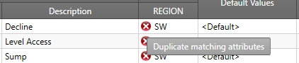
If it is not possible to create unique combinations of matching attributes for existing definitions, non-unique value combinations will be highlighted in the definitions table, for example:
The Solid colour will be taken from the design file, regardless of whether COLOUR is used in the attribute matching or not.
How Mapping Attributes are used in Generating Definitions
The Generate Design Definitions function is a useful tool that allows you to extract information from external files and use it to construct design definitions automatically.
This panel also honours the current mapping attributes to automatically extract definitions from the selected file. For example, if your mapping attributes are LSTYLE, COLOUR and SYMBOL, the Generate Design Definitions panel will automatically construct definitions based on all combinations of values found for these attributes in the file.
See Mapping Attributes.
See Generating Design Definitions.
Using the Apply Design Definitions Panel
The Apply Design Definition panel is split into four tabs; one for each of the project design types (Fixed Cross Section, Outline, Complex Solid and Wireframe).
The contents of these tables can be sorted by selecting one of the column headings, but are otherwise read-only (you can configure your design definitions using the Edit Definitions panel).
Tip: Display the Edit Design Definitions panel
at the same time as the Apply
Design Definitions and other panels. Changes made to the
definitions are instantly reflected in the Apply
Design Definitions panel when definition changes are committed.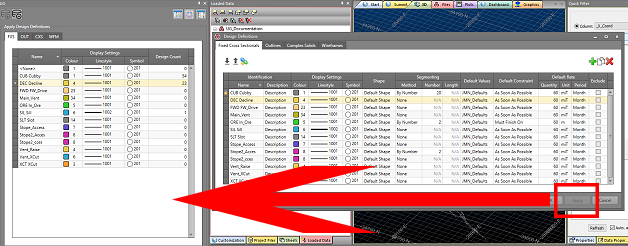
Note: If WFM definitions are grouped, this grouping is reflected in the definitions table. See Imported Wireframes.
You can choose to load your design files into the 3D window, or unload them if already loaded, using the controls in the top left corner of the panel:

- Load design files: all design files for the currently selected design type tab (FXS, OUT, CXS or WFM) will be loaded. This mode remains active and, depending on the commands that are subsequently run, may cause the loaded data to be updated automatically.
- Unload design files: this will unload any currently displayed objects from the 3D window. Whilst data on disk is unaffected, unsaved changes can be lost, so you will need to confirm your decision to unload data. This mode remains active - panel actions cannot not enforce the loading and display of design type data.
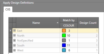
The Definitions Table
Each design definition is summarized on the Apply Design Definitions panel. Not all definition parameters are displayed here (for the full view, you can display the EditDesign Definitions panel, accessible using the Edit Design Definitions button at the top of the panel).
The summary information for each definition is:
- Name: the unique name that denotes the definition. You cannot duplicate these names during definition editing.
- Colour: the current Datamine colour index for the definition. This parameter is used for display purposes only.
- Linestyle: the current linestyle used to display data assigned to the design definition. This parameter is used for display purposes only.
- Symbol: the symbol
used to display data assigned to the definition. This parameter
is used for display purposes only.
(As mentioned above, the Colour, Linestyle and Symbol values do not have to be unique for the current project as in legacy underground planning products). - Design Count: how many object entities that use the definition. If zero, it means that the definition is not currently used in the project. This value is updated dynamically as definitions are applied or removed from your data, so is always up to date.
Applying Definitions to Data
Existing definitions can be applied by selecting a definition in the displayed table to highlight it, then applying it to data . You can either preselect data and apply it only to the selected items (Apply to Selected), or you can apply to everything that is currently in view (Apply to Visible). Data that is displayed, but clipped by the current 3D window frame is still considered to be 'visible'.
Tip: You can use the general data display filtering options (the Quick Filter control bar, options on the Format ribbon or direct command access) to filter the current 3D view based on existing attributes and values. Used in conjunction with the Apply to Visible function, this makes it easy to apply definitions to a specific subset of the currently loaded design data.
Once definitions have been applied to design data, it can be committed to the underlying data object using Save Designs. This will update the current project design files with the latest design definitions.
Note: More than one wireframe can be selected at a time.
Display Options
If design data is loaded (see above), the following options are available for controlling when and how data is displayed.
Filter using selected definition: if selected, the display will update to show only design data that corresponds to the selected definition. If the Design Count for a definition is zero, nothing will be displayed. If this option is disabled, all design data of the selected design type will be displayed, regardless of the currently selected definition.
Zoom all when filter changes: if selected, the 3D window will be automatically scaled to show all visible data each time a definition is either selected, applied or unapplied. This can be useful to highlight an area of interest, or to isolate and scale the view to show all data that carries a particular definition (if used in combination with the Filter using selected definition option above).
Show Tag Strings (CXS only, after loading design data): if selected, any tag strings that form part of the complex solids design strings will be displayed with the other CXS strings in the 3D window. If disabled (default), tag strings will be hidden.
Design String
Sequence (CXS only, after loading design data): you can display
the order in which complex solid segments will be sequenced during
processing. Enabling the Show design
string sequence check box will automatically add a numeric
label to the centre of each complex solid segment, indicating the
numeric sequence in which they will be processed, ultimately indicating
the mining direction. The sequence will be calculated based on the
CXS design definition (specifically, the nominated Mining
Direction).
For example, complex solid design definitions configured like this:
Could produce CXS sequencing like this: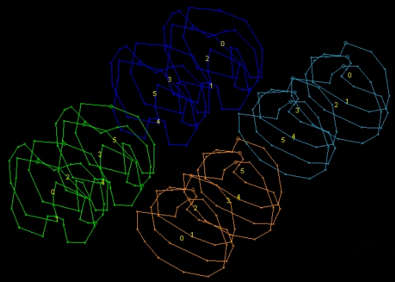
If changes are made to complex solid design definitions, you can update the on-screen sequence labels using the refresh button on the right.
Utilities and Tools
The Apply Design Definitions panel is also a gateway to the following supporting panels. All of these can be displayed at the same time and changes made in one are instantly reflected in partner controls in other display dialogs.
For example, you can display the Apply Design Definitions, Edit Design Definitions and Shape Editor panels. This allows you to set up your design definitions (either by generating from files or manual editing), define cross sectional shapes for your FXS data and apply the new definitions without having to open or close any panels. If you're using multiple monitors, spread them out and you can everything you need at your fingertips.
The functions you can access are:
-
Edit Design Definitions: generate and/or define what your design definitions represent. See Edit Design Definitions.
-
Edit FXS Shapes: define your FXS profile shapes here. See Edit Shapes.
-
Edit Default Values: This screen is used to setup default values for a block model See Edit Default Values.
Related topics and activities